

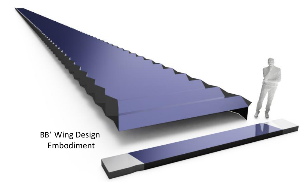
The Unifold folding method
Unifold introduces a method for folding non-developable surfaces into regularly shaped envelopes with high internal and external volume packing. It enables both conical and hyperbolic deployed surface geometry using exclusively concave major-crease disruptions in higher-order Z-folded sheets.
The technical contribution is the folding method: the combination of deployed geometry, coordinated unfolding, and compact, regular stowage. Internal packing describes how completely the folded stack is filled by the surface material; external packing describes how efficiently that stack fills a regular bounding volume. The deployed shapes can include familiar forms, such as eggbox tessellations. Part 1 presents the geometry, joints, folding process, and general embodiments. Part 2 uses space structures as one application example, showing system configurations and the resulting mass and volume performance estimates.
The geometric discussion is intended to encourage exploration by the origami and kirigami research community. Novel embodiments, new directions, and designs that improve on those presented here are welcome. Sharing the pattern and its behavior is intended to help others discover what more can be made from these ideas.
Degrees of Freedom’s patent-pending work concerns the application of Unifold to deployable structures, including apertures, shelters, and shields for terrestrial and space use. The aerospace discussion here focuses largely on solar arrays, with radiators as a further example; it is one case study within that broader application context.
Part 1 · The folding method
Unifold: folding non-developable surfaces
The folding problem
Fabricating non-developable surfaces from flat sheets is difficult, and folding them rarely preserves both complete internal stack packing and efficient packing within a regular external volume. This limits the practical use of complex surfaces when manufacturing and mechanism complexity matter.
The desired combination is complete internal stowed packing, a one-degree-of-freedom or non-tangling deployment path, a prescribed non-developable deployed surface, and complete packing within a regular bounding volume. Regular surface shapes, fabrication from a flat sheet, and joints without offsets make the geometry easier to use in real assemblies.
These are geometric targets. A physical structure must also accommodate finite thickness, joint clearances, materials, and operating loads.
Comparison with other folding methods
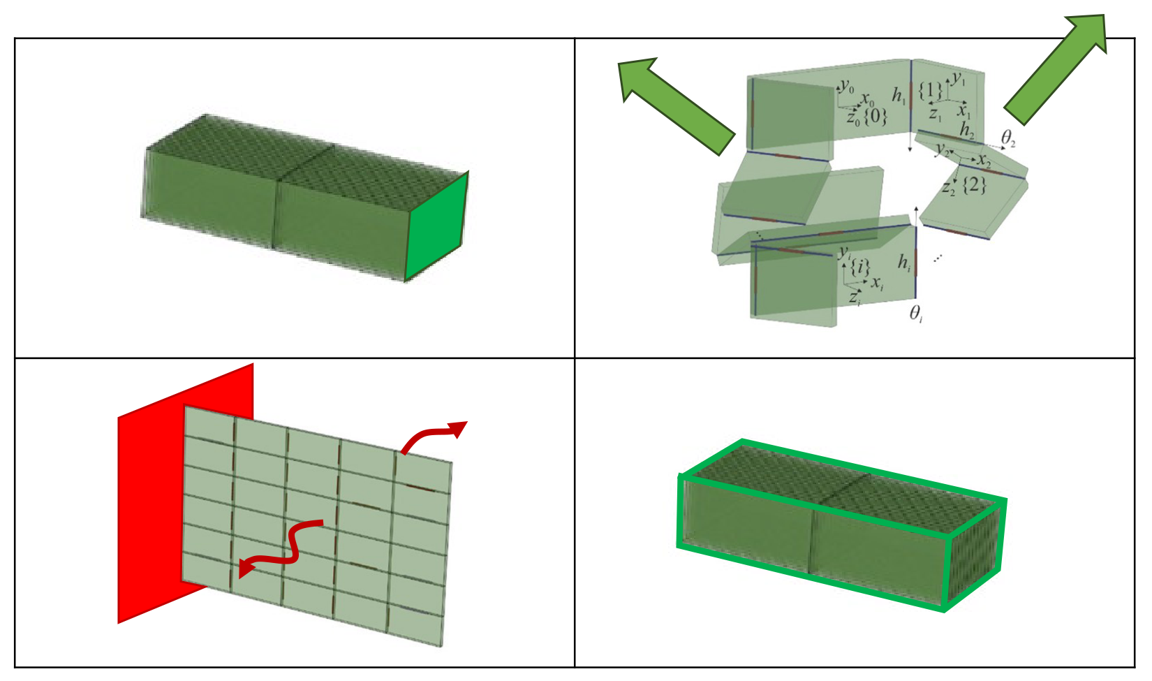
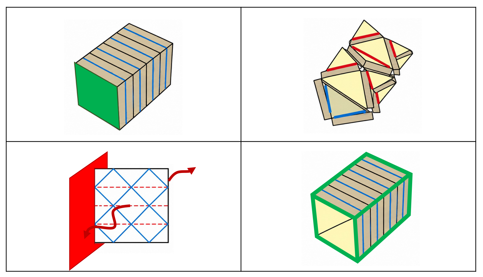
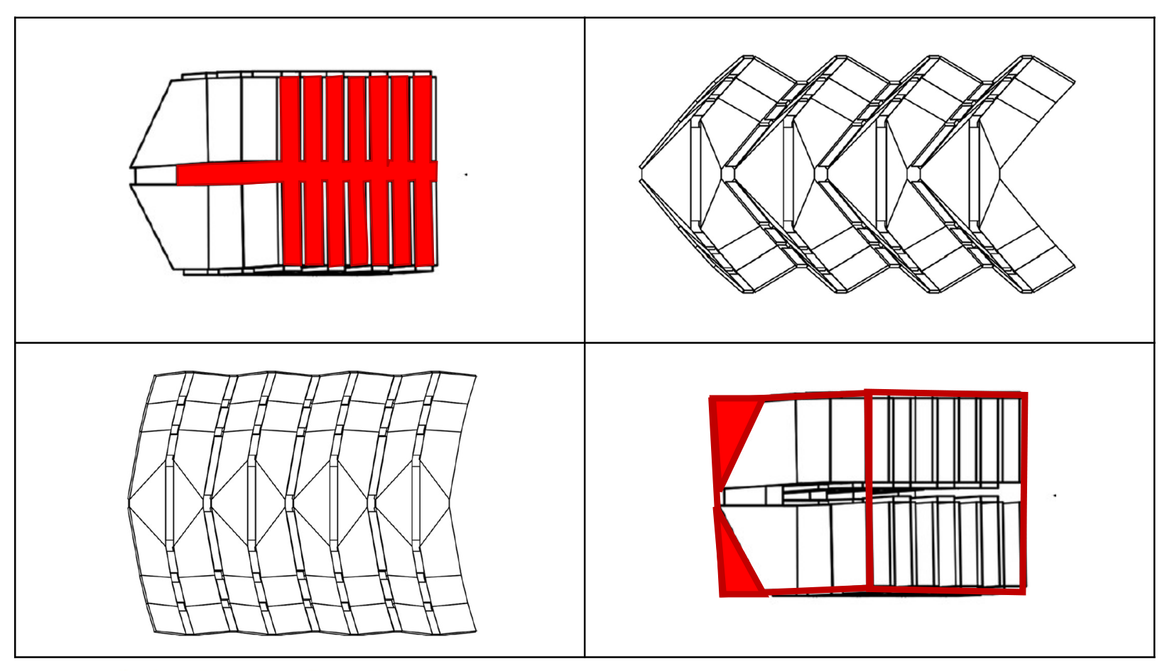
Alternative patterns illuminate the trade between packing, deployment control, and structural geometry. The comparisons below apply the same geometric requirements to each example. Red and green comparison annotations identify limitations and favorable attributes; the research sources for the underlying images remain attached to the figures.
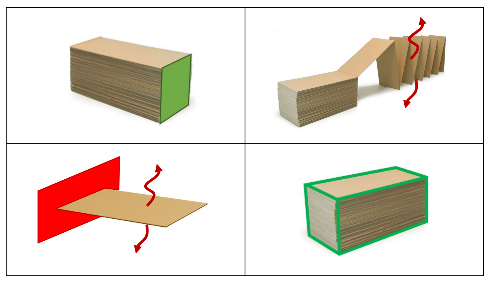
Z-fold: unconstrained deployment and a flexible surface
The z-fold packs both the material stack and its regular bounding volume efficiently. In the illustrated arrangement, deployment is uncontrolled and the deployed surface remains developable, leaving deformation modes resisted by weak local membrane bending.
Eggbox: poor external packing
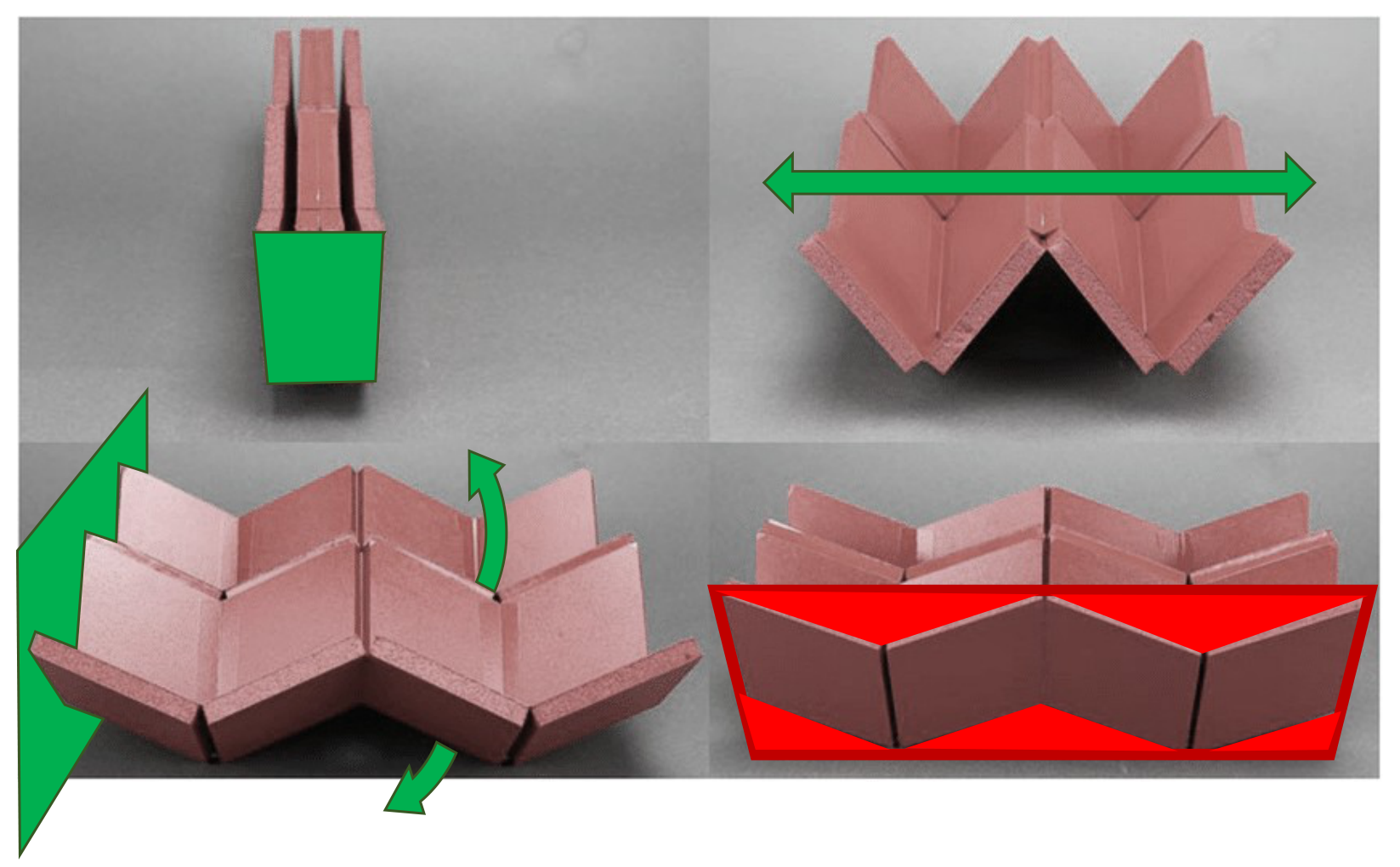
Eggbox combines efficient internal packing, one-degree-of-freedom deployment, and non-developable deployed geometry. Its irregular stowed envelope leaves unused space inside a regular bounding volume.
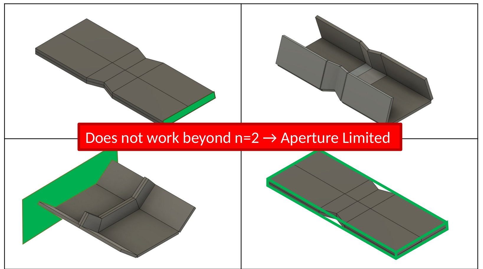
Inboard eggbox: limited Z-folding order
The illustrated inboard eggbox has complete internal packing, one-degree-of-freedom deployment, a non-developable deployed surface, and practically complete packing within a regular bounding volume. Its limitation is folding order: the illustrated construction does not extend beyond n = 2. Moving the concave disruptions inboard therefore improves packing but does not, by itself, permit a large aperture made from repeated Z-folds.
Hamiltonian circuit
The Hamiltonian-circuit example combines efficient internal and external packing with sufficiently stable deployment. The deployed surface remains developable, so deployment control does not resolve its thin-membrane local-bending weakness.
Yoshimura: low deployed stiffness
The Yoshimura example similarly combines compact packing and sufficiently stable deployment, but retains developable geometry and local-bending paths rather than finite section depth throughout the aperture.
Waterbomb: poor volume packing
The waterbomb/eggbox combination provides non-developable structure and sufficiently stable deployment. Its internal stowed packing is assessed here as below 50%, and its external packing is poor within a regular bounding volume. A lower-aspect-ratio stowed envelope is a useful countervailing attribute.
Bloom patterns
Bloom patterns are radially expansive, developable, and flat-foldable. They offer another approach to compact surface deployment, but developability remains a limitation for the thin-membrane structural objective considered here.

Thick-panel origami
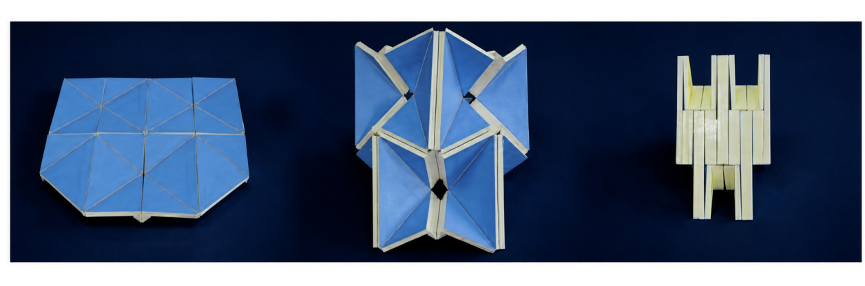
The blue thick-panel waterbomb shown below is one design in three folding states. It illustrates how finite panel thickness can be accommodated throughout folding; the added mechanical complexity must be weighed against system-level performance.
The manufacturing approach can combine cutting, folding, and bonding to produce the required articulated shell geometry. Simplicity is an optimization objective: geometric novelty should earn its place through improved system performance.
The Unifold folding method
Unifold introduces exclusively concave major-crease disruptions into higher-order Z-folded sheets. The joint geometry and coordinated folding sequence allow both conical and hyperbolic deployed surface shapes while preserving high internal stack packing and high external packing within a regular stowed envelope. The distinction between the disruption geometry and the deployed vertex geometry is central to the method.

| Requirement | Z-fold | Eggbox | Unifold |
|---|---|---|---|
| 100% packing of surface material stack | Yes | Yes | Yes |
| 1-DOF or non-tangling deployment | No | Yes | Yes |
| Prescribed non-developable surface | No | Yes | Yes |
| 100% packing in regular bounding volume | Yes | No | Yes |
| Regular panel shapes | Yes | Yes | Yes |
| Fabrication from a flat sheet | Yes | No | Yes |
| No offset joints | Yes | Yes | Yes |
Vertex consolidation and deployed curvature
Along the major creases, the stowed arrangement uses facing conical joints. Half of these must contribute hyperbolic geometry in the deployed arrangement. Higher-degree vertices introduce segments whose angles are added or subtracted during consolidation. In the illustrated construction, adjacent four-degree vertices consolidate into an effective hyperbolic vertex.
At detail A, θ₁₂ = θ₂ − θ₁: subtraction accentuates the conical geometry. At detail B, θ₁₃ = 180° − θ₂ + θ₁: addition produces the illustrated hyperbolic deployed geometry. The diagrams describe the effective sector-angle combinations of the consolidated joints.
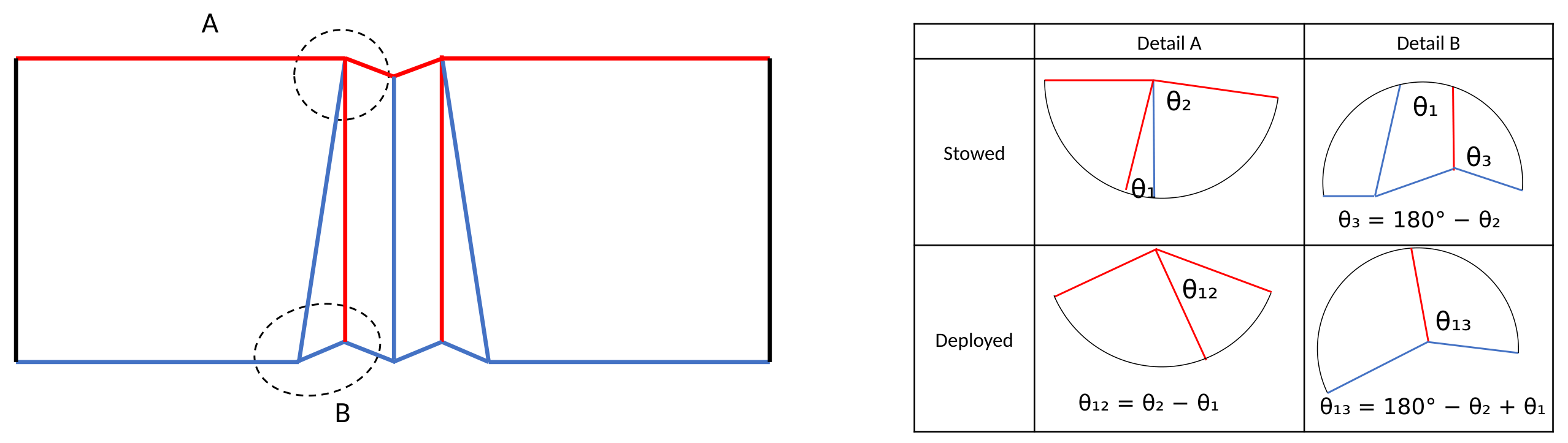
The process starts with higher-order vertices. Synchronization through the surrounding network constrains their effective motion to linked four-bar mechanisms with one collective degree of freedom. Segment contact can further consolidate the mechanisms into effective three-bar linkages at full deployment, removing the remaining mechanism freedom. Elastic deformation of the panels and joints remains possible under load.
Conical vertices can therefore participate in creating hyperbolic deployed surfaces. Some resulting configurations can also reverse-fold using their now-hyperbolic effective vertices, reaching a different stowed envelope. The deployed surface itself need not be novel: Unifold changes how it can be fabricated, packed, and unfolded.
Surface nomenclature
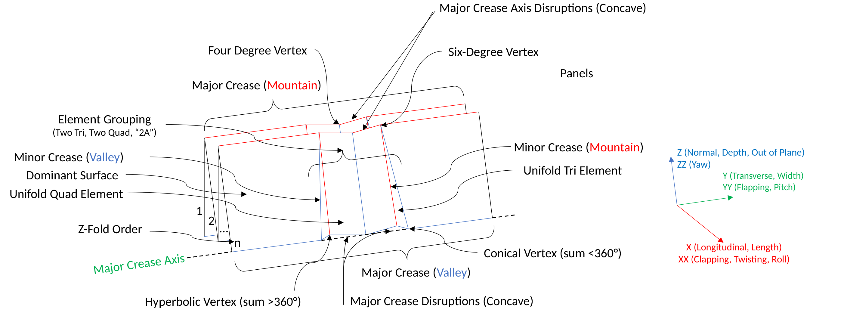
Major and minor creases define the panels, elements, and connections. The diagram identifies concave major-axis disruptions, four- and six-degree vertices, the dominant surface, and the Z-fold order n. Conical vertices have sector-angle sums below 360°; hyperbolic vertices have sums above 360°. X, Y, and Z identify longitudinal, transverse, and normal directions.
Elements, groups, and synchronization
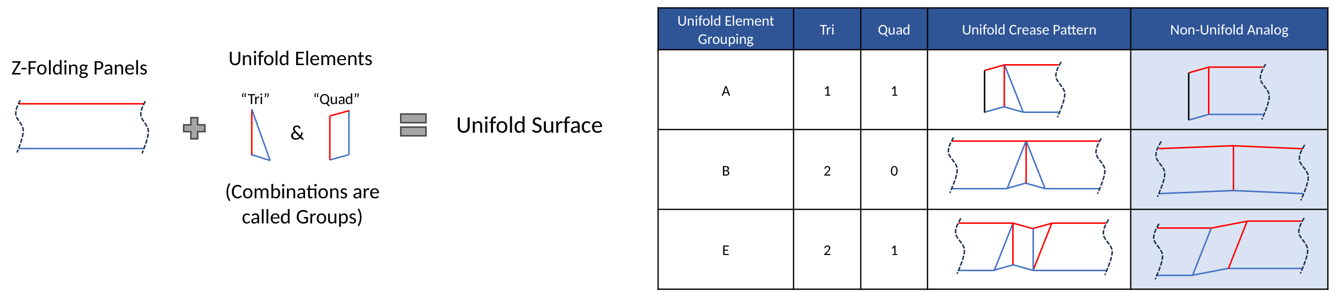
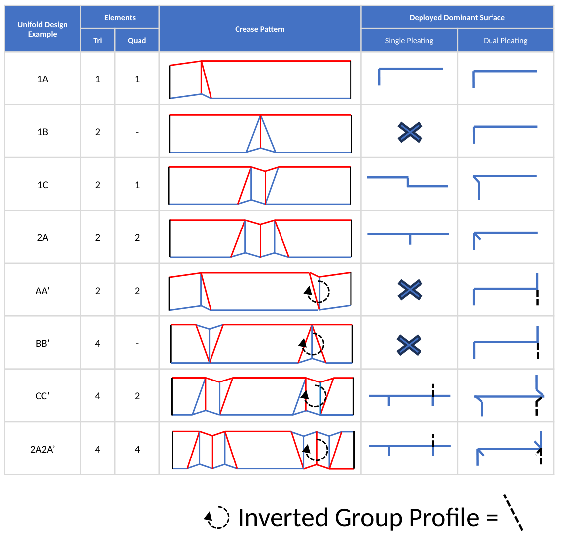
Groups modify a Z-folding surface through collections of creases. Each group contains at least two elements, including at least one triangular Tri element. Quadrilateral Quad elements complete the illustrated combinations. Tri elements provide the opposing segment-angle contributions used to set deployed vertex geometry. Groups sit between major axes and create at least one major-axis disruption.
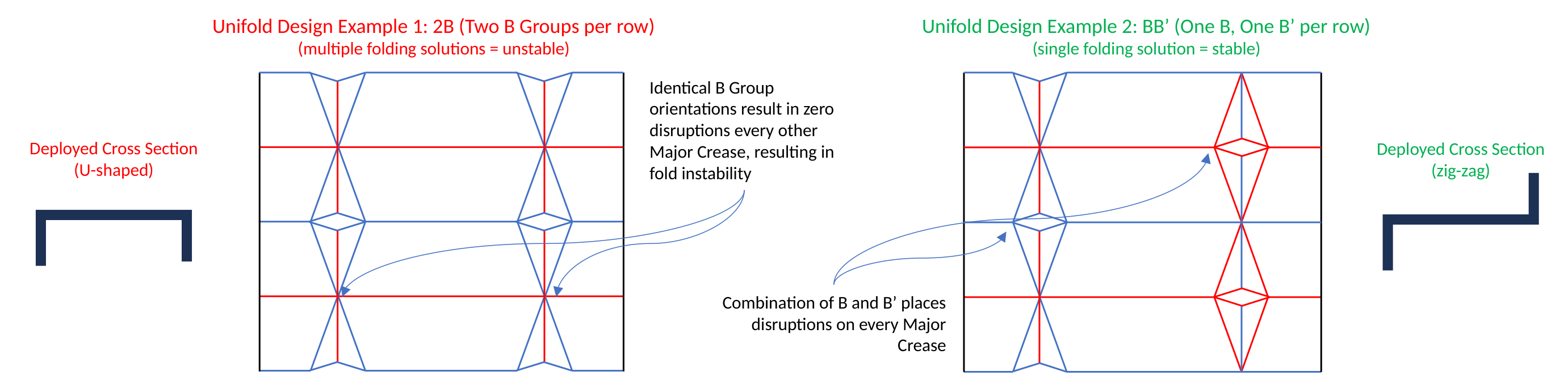
Group orientation affects the folding solution. Two identically oriented B groups leave every other major crease undisrupted and admit multiple folding solutions. Combining B with its inverted form B′ introduces disruptions on every major crease in the illustrated arrangement, producing a single coordinated folding solution.
Curves, loops, and deployed sections
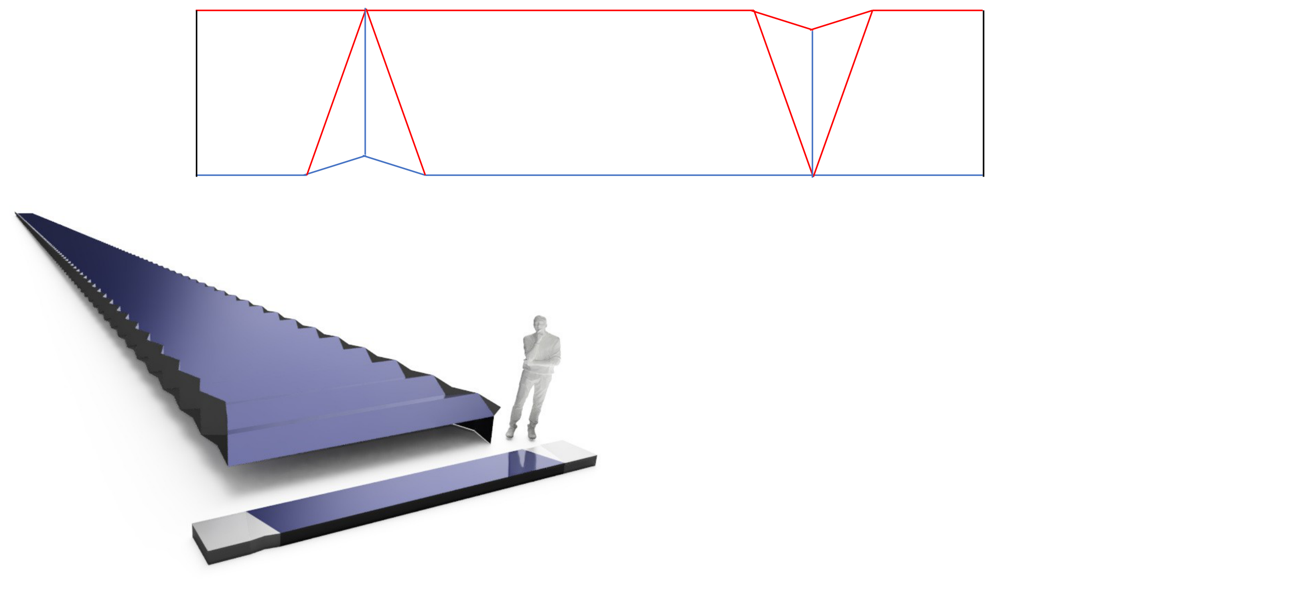
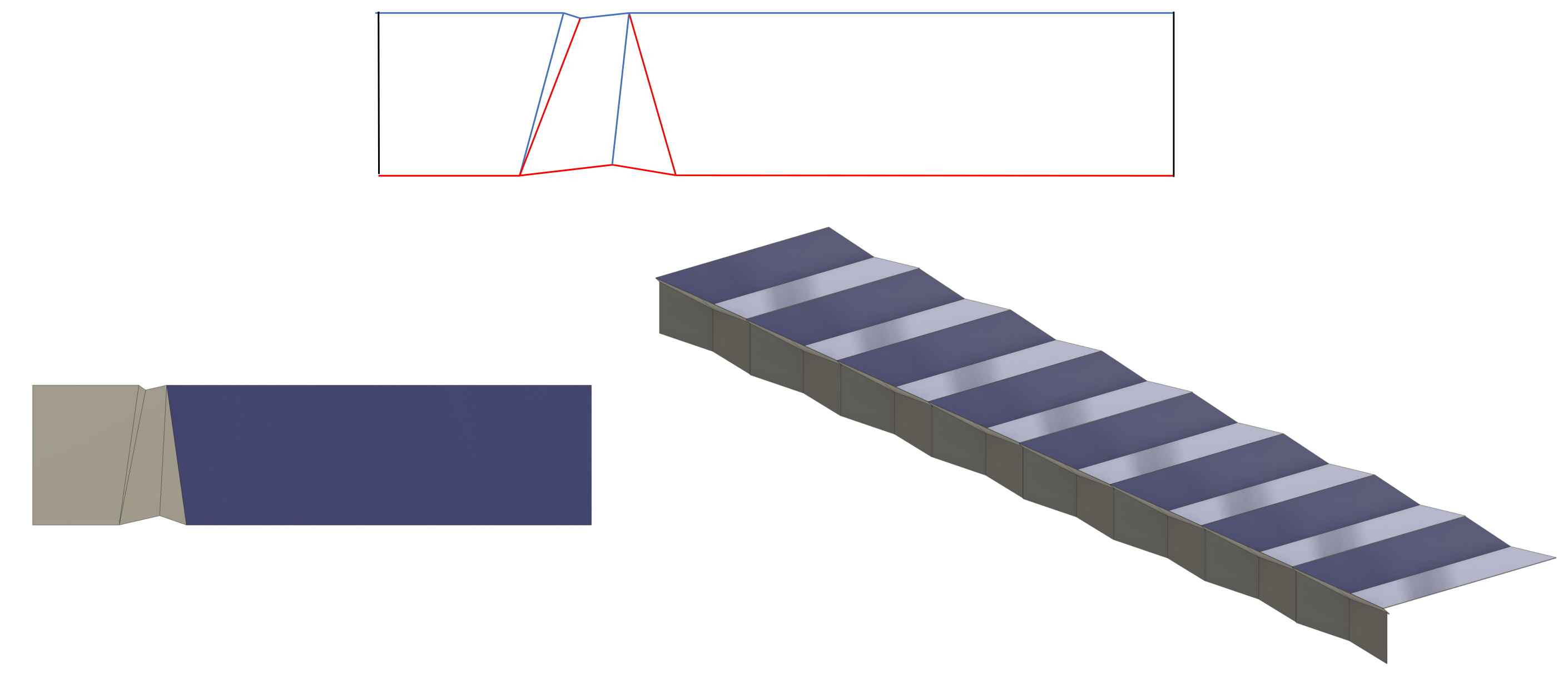
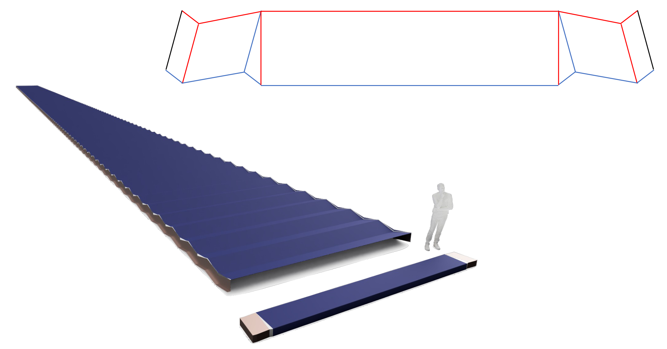
Angles within the groups control the deployed shape. Off-parallel major crease axes in Quad elements produce pitch curvature; off-parallel panel major creases produce yaw curvature during extension. Related angle changes produce turning, looping, single pleating, and dual pleating.

Configured examples are identified by the labels shown in the figure, including 1A, 1B, 1C, 2A, CC′, and 2A2A′. A prime denotes an inverted group orientation. Repeating BB′ can deploy into an eggbox tessellation. Crease angles within a grouping can significantly change the deployed dominant surface.
Element contact, latching, and deployed stability
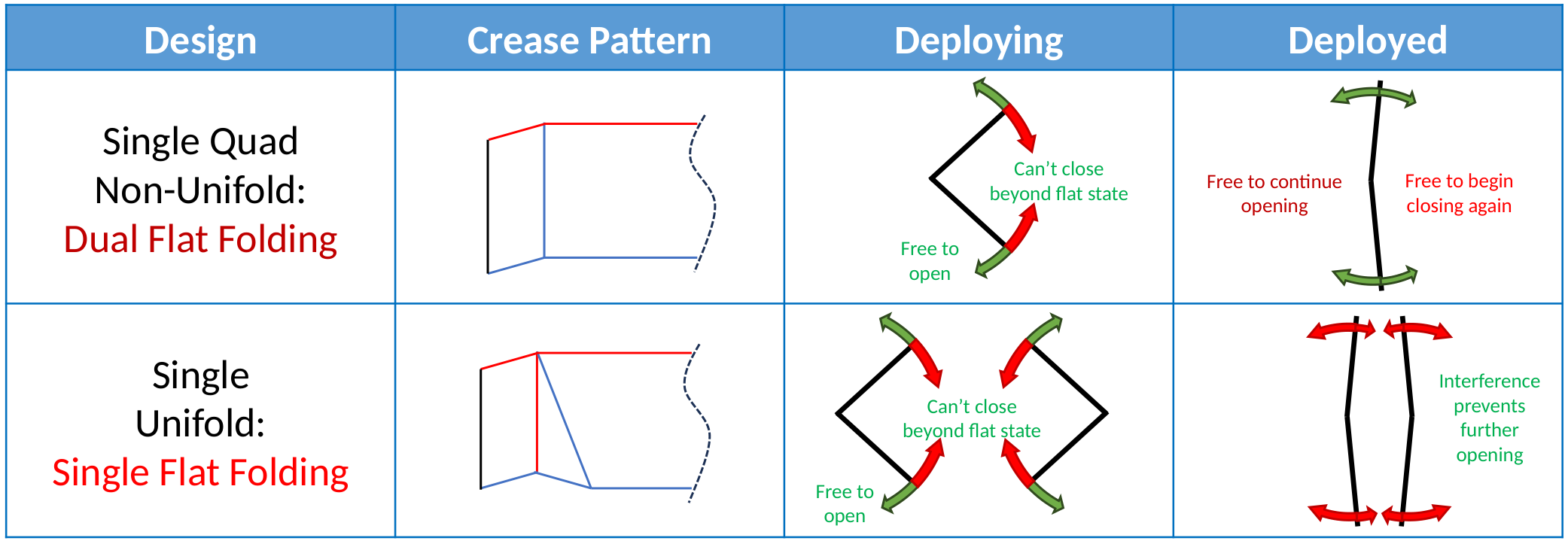
Contact between segments limits joint over-rotation and controls the fully deployed state. The comparison distinguishes a single Quad reference that can pass through a deployed state and continue toward a second flat-folded state from the illustrated Unifold configuration, whose segment interference prevents further opening. The configuration and its contacts determine which folding paths remain accessible.
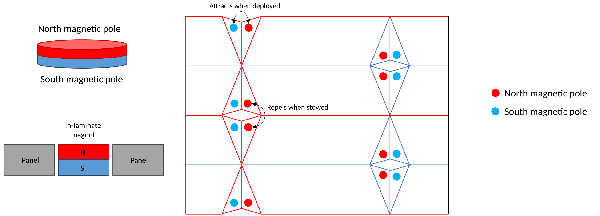
Interleaving extensions of adjacent panels further resist Euler buckling of coplanar plates. Magnetic attraction between tangentially facing surfaces can resist thin-rail separation. The illustrated pole arrangement attracts when deployed and repels when stowed, helping initiate separation without supplying all of the energy required for global deployment.
Fabrication from a flat sheet
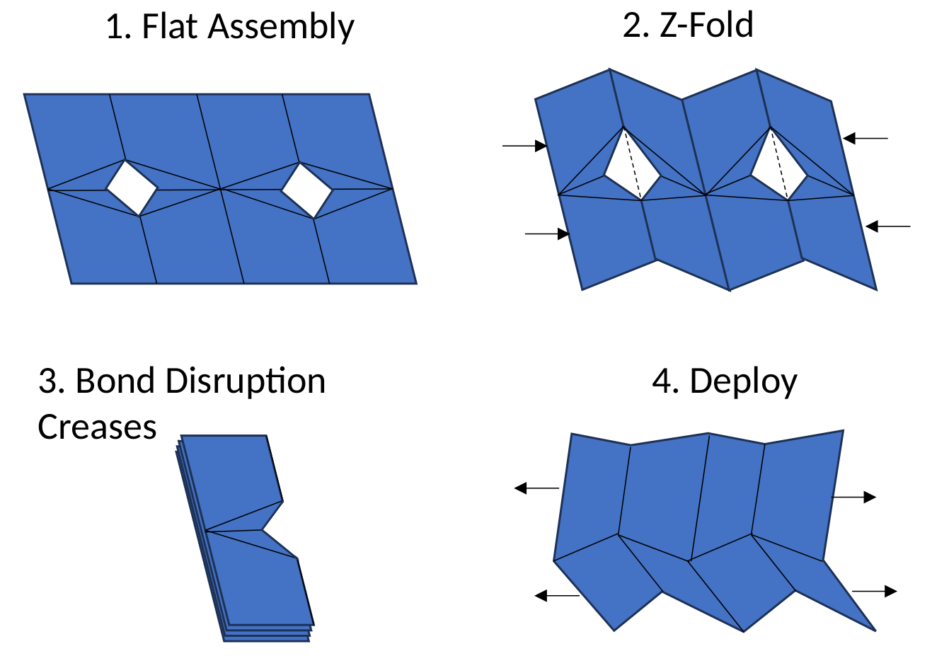
The fabrication sequence begins with openings spanning selected major creases. Z-folding aligns the disruption creases, which are bonded while folded. Re-expansion articulates the completed network and produces the intended non-developable surface. Cutting and bonding are fabrication operations; Unifold is described here as an articulated shell structure.
Regular stowed packing also makes the complex surface accessible through flat-sheet fabrication. This creates a route to integrating the folding mechanism into the surface and reducing the need for separate hardware.
General design examples
The following embodiments illustrate different deployed sections and planforms, together with their corresponding crease patterns and stowed configurations.

Part 2
Space Application
Space structures are one example application of the folding method. The following sections establish a common benchmark, show photovoltaic, combined photovoltaic–radiator, and concentrator configurations, and estimate the performance preserved through integration. These application results are secondary to the folding method presented in Part 1.
Preserving active-surface performance
The space case study asks how much of an active surface’s mass-specific and volumetric performance can be preserved when it becomes a deployable structure. Solar arrays provide the numerical example; combined photovoltaic and radiator surfaces and a V-trough concentrator illustrate other configurations.
The common active-stack assumptions are listed in the baseline table below. They include the photovoltaic material and environmental coverings. The folding architecture reduces the additional mass and stowed volume needed to arrange, deploy, and support that surface.
Unifold places deployment kinematics and structural geometry within the surface. Major-crease disruptions give the deployed shell finite section depth, reducing reliance on separate support members and mechanisms. Under the stated assumptions, the 2A example preserves approximately 84% of module mass-specific performance and 83% of module volumetric performance, including the pleating cosine loss.
The ideal surface and the overhead of arranging it
A bare active surface is the performance reference. Every provision for deployment and support consumes some mass, volume, or area. Its purpose is to make the surface’s arrangement deterministic under finite loads and movement, locally between elements and globally across the aperture. The required degree of control depends on the application.
Section depth and projected area
Creating section depth increases the surface area required for the same projected aperture. At fixed material thickness and density, the additional area increases mass and stowed material volume proportionally, reducing aperture-based active-surface performance by the corresponding cosine factor. Low pleating angles, 15° or below, keep this loss small while large panels can still produce deep sections. This projection penalty applies to the solar example; radiator performance also depends on emission geometry and view factors.
Active surface fraction as a performance measure
If active and inactive regions have comparable thickness and density, their area fractions also approximate their mass and material-volume fractions. With negligible additional hardware, assembly W/kg equals active-stack W/kg multiplied by active surface fraction and the geometric yield of the deployed surface. For solar arrays illuminated normal to the overall aperture, pleating introduces a cosine factor. Assembly volumetric power density additionally includes the packing fraction within the stowed envelope.
Differences in regional thickness or density, unused packing volume, and discrete hardware must be included when significant. These assumptions make surface allocation a useful first-order performance estimate, while keeping the remaining integration overhead explicit.
Benchmarking assembly performance
The following active-surface baseline is used throughout the solar comparisons.
| Quantity | Value | Calculation |
|---|---|---|
| Areal mass | 1 kg/m² | Assumed |
| Stack thickness | 700 µm | 700 µm |
| Electrical output per area | 225 W/m² | Assumed |
| Mass-specific power | 225 W/kg | 225 / 1 |
| Volumetric power density | 320 kW/m³ | Rounded from output per area divided by thickness |
Performance estimates are rounded. Minimizing non-active overhead preserves a larger fraction of the constituent technology’s performance.
Pantograph boom and blanket benchmark
K2 Space promotional photographs and video captures provide a visual reference for a pantograph boom and blanket architecture. The annotated geometry is used here to estimate the fraction of the stowed envelope occupied by active blanket material. The volume estimate combines the relative projected areas of the stowed blanket assembly and boom with the folded-blanket-to-assembly thickness ratio. It yields an estimated active volume fraction of approximately 12%. A separate rule-of-thumb assumption assigns 25% of assembly mass to the blanket.

| Architecture | Active mass fraction | Active volume fraction | W/kg | kW/m³ |
|---|---|---|---|---|
| Boom and blanket benchmark | 25% | 12% | 56 | 38 |
The estimated boom-and-blanket performance is approximately 56 W/kg and 38 kW/m³, retaining 25% and 12% of module performance respectively. These estimates use promotional imagery and assumed fractions; they are not published K2 performance specifications. An integrated satellite platform must also account for its other subsystems.
Configured solar arrays and radiators
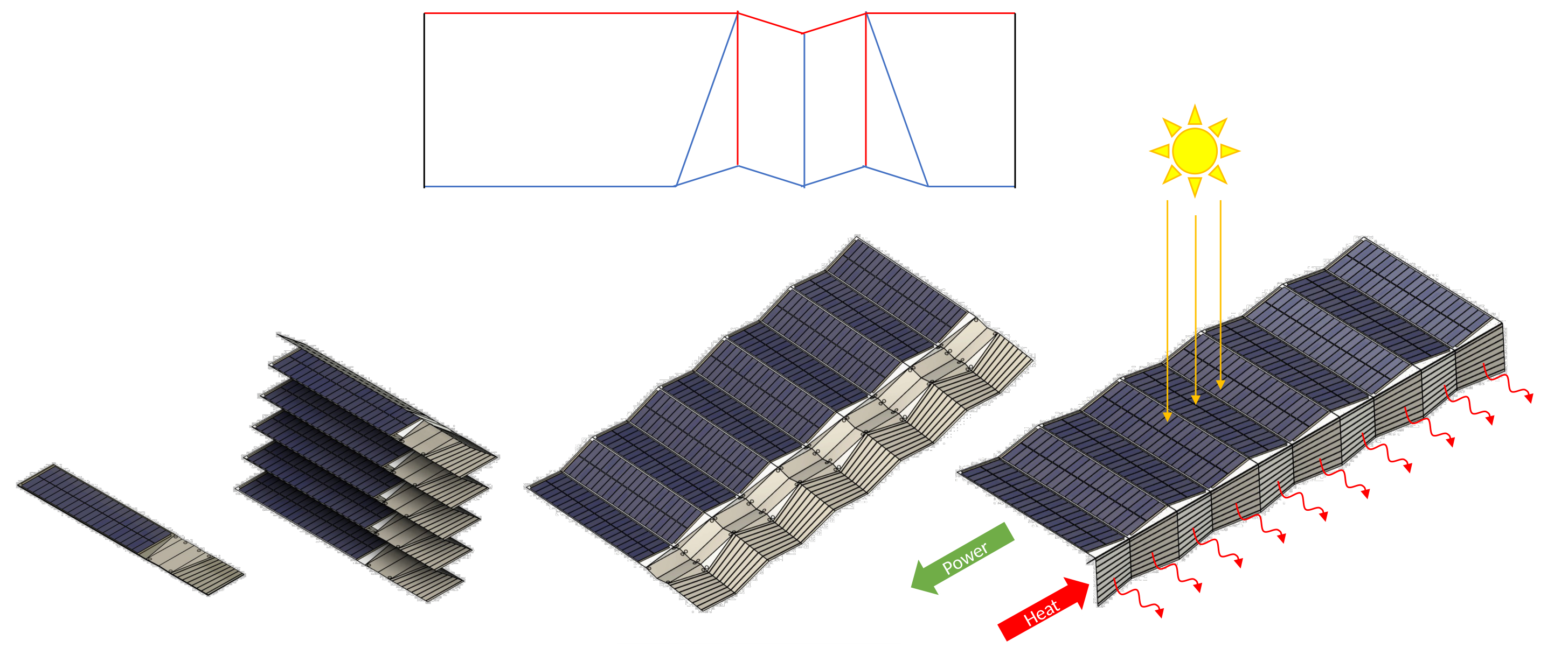
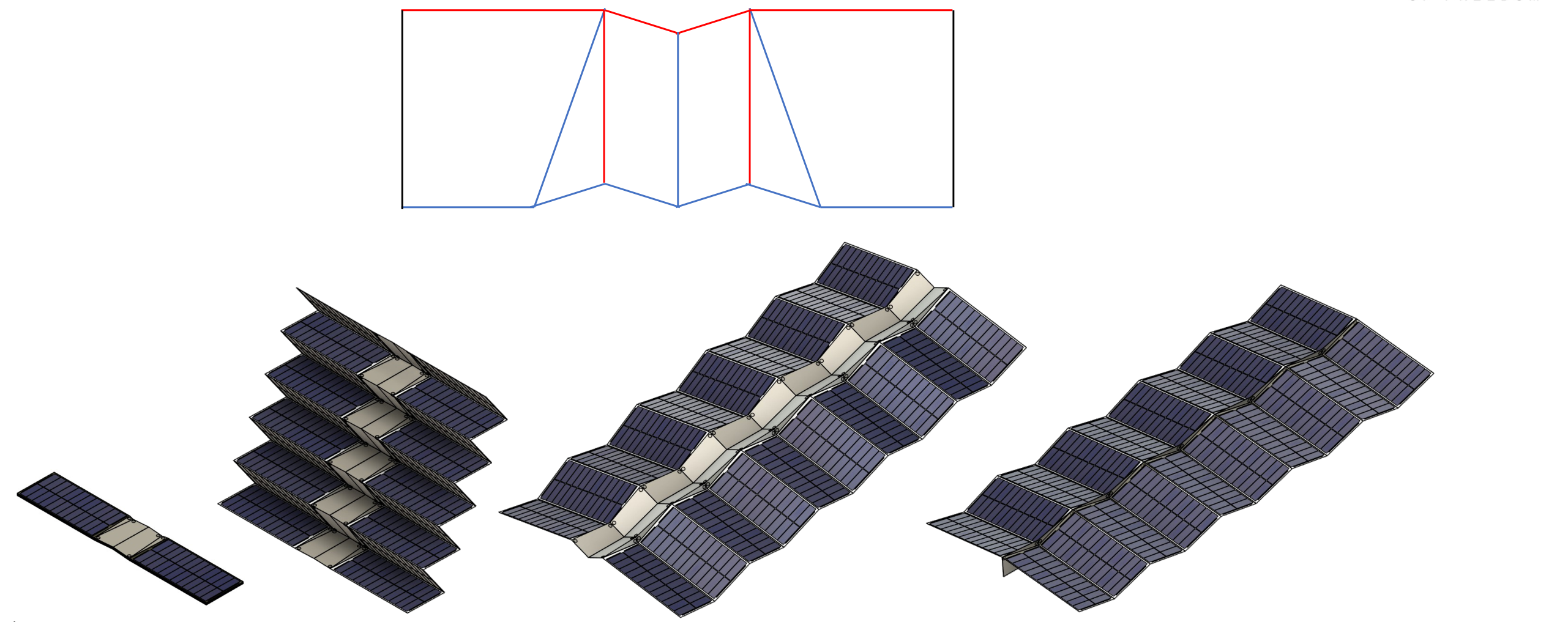
The 2A geometry can be configured as a functional system by incorporating photovoltaic and radiator surfaces. The examples below show combined power generation and heat rejection, followed by a photovoltaic-only configuration. The sequences show a compact stack opening into an aperture, with active regions carried by the panels. In the combined example, yellow rays indicate sunlight, the green arrow indicates electrical power, and red arrows indicate heat.
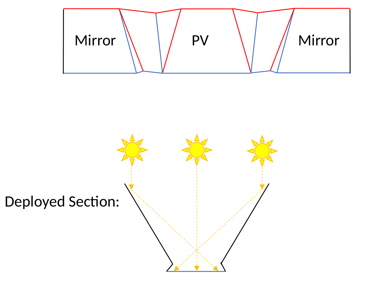
2C photovoltaic concentrator
The 2C example forms a V-trough with mirror surfaces directing sunlight toward a photovoltaic region. It illustrates another way to assign functional surfaces to a folded geometry.
2A performance example
The revised 2A point design assigns 86% of the total surface to active area and achieves 99% packing within the regular stowed bounding volume. Quad group elements serve as harness regions, and edge elements help resist rail buckling. The remaining surface area supports these structural and integration functions. The 10° pleating introduces approximately 2% cosine loss; this estimate uses a rounded 98% projected-area yield. These fractions are geometric assumptions for the illustrated embodiment.

With uniform areal mass, multiply module mass-specific power by the 86% active surface fraction and 98% cosine yield. For volumetric power density, also apply the 99% stowed packing fraction. The estimates below concern the surface assembly; additional hardware and application-specific requirements must be included in a complete system.
| Assembly | W/kg | kW/m³ |
|---|---|---|
| Boom and blanket benchmark | 56 | 38 |
| Revised 2A model | 190 | 267 |
| 2A / boom-and-blanket benchmark | 3× | 7× |
At equal delivered power, these assumptions imply approximately 70% less mass and 86% less stowed volume than the boom-and-blanket benchmark. The active material supplies the performance. Unifold’s contribution is to preserve it through integration, a benefit that scales with the constituent technology rather than depending on a particular type of solar cell.
Prototype validation
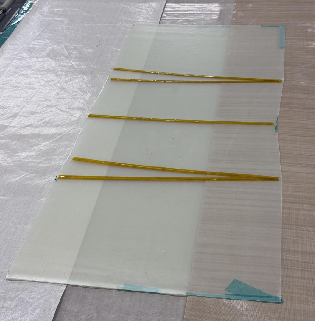
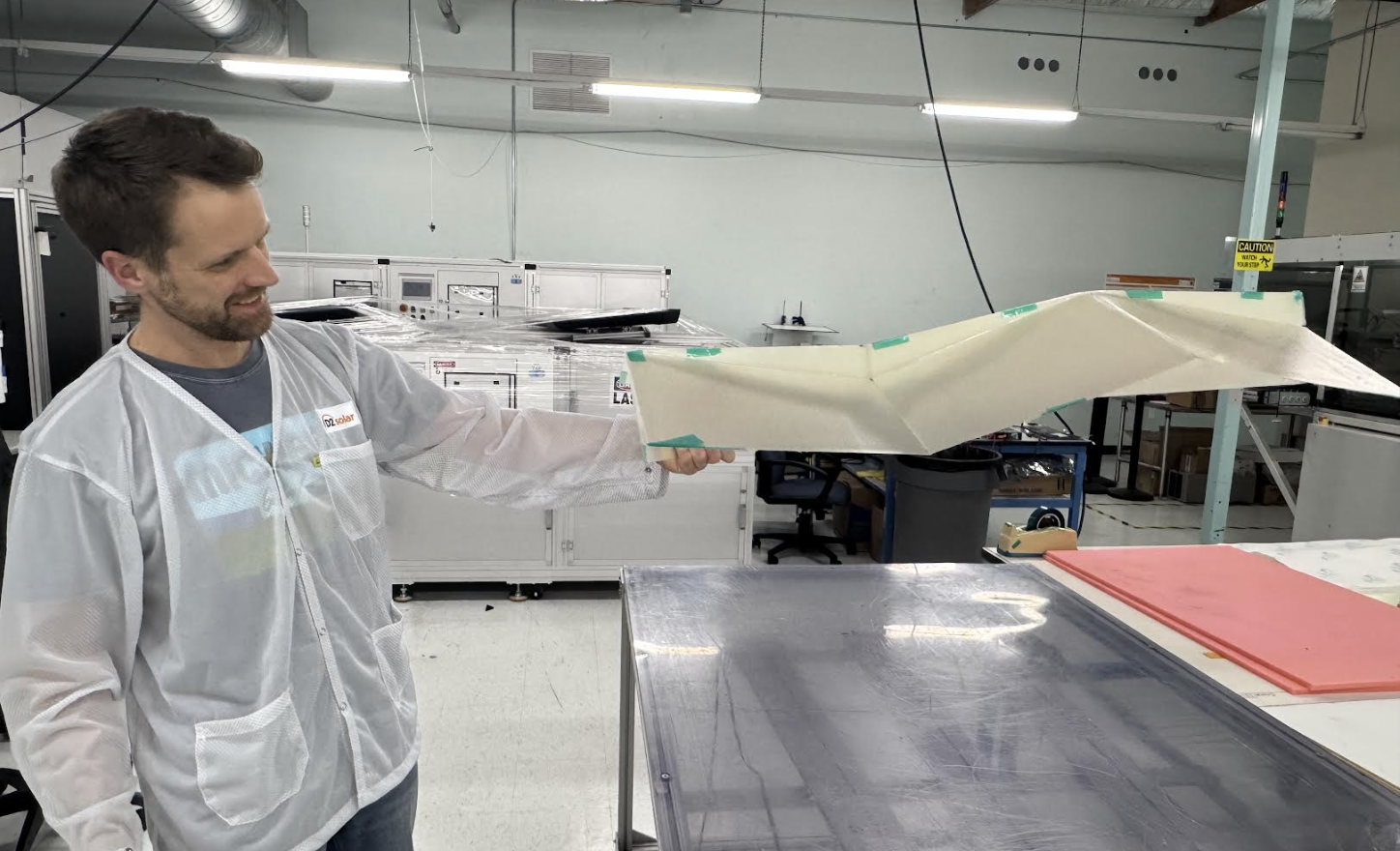
Physical 2A prototypes tested the progression from making and articulating the laminated surface to arranging a larger deployed aperture. MK2 validated assembly and articulation using flight-like construction. MK3 extended the demonstration to local groupings positioning a global aperture.
MK2: laminate assembly and articulation
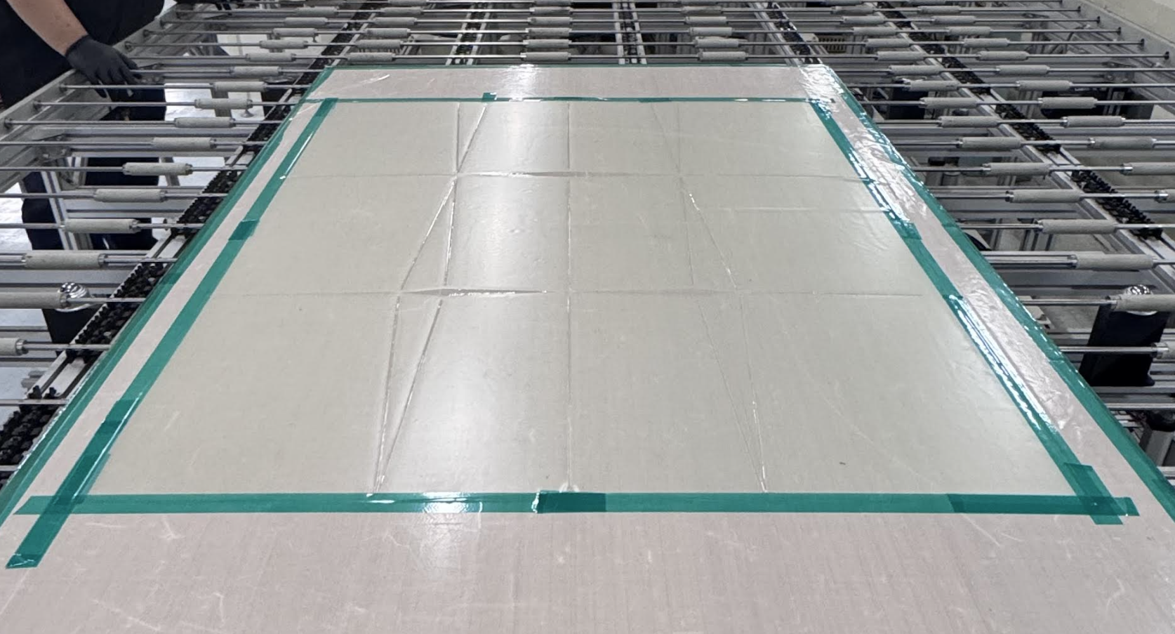
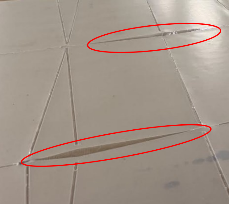
Garolite facesheets provided analogs for panel mass and stiffness. Continuous internal POE and ETFE layers spanned the panels and joints, forming living hinges between discrete Garolite panels. The resulting laminate was 1 mm thick.
The prototype successfully demonstrated assembly and articulation of the surface structure. The deployed photograph shows the structure under terrestrial gravity. The principal finding was the need to control spine-panel coplanarity to obtain the intended arrangement.
Flat lamination
2A crease disruptions
Bonded and stowed
Deployed under 1 g
MK3: arranging a full aperture
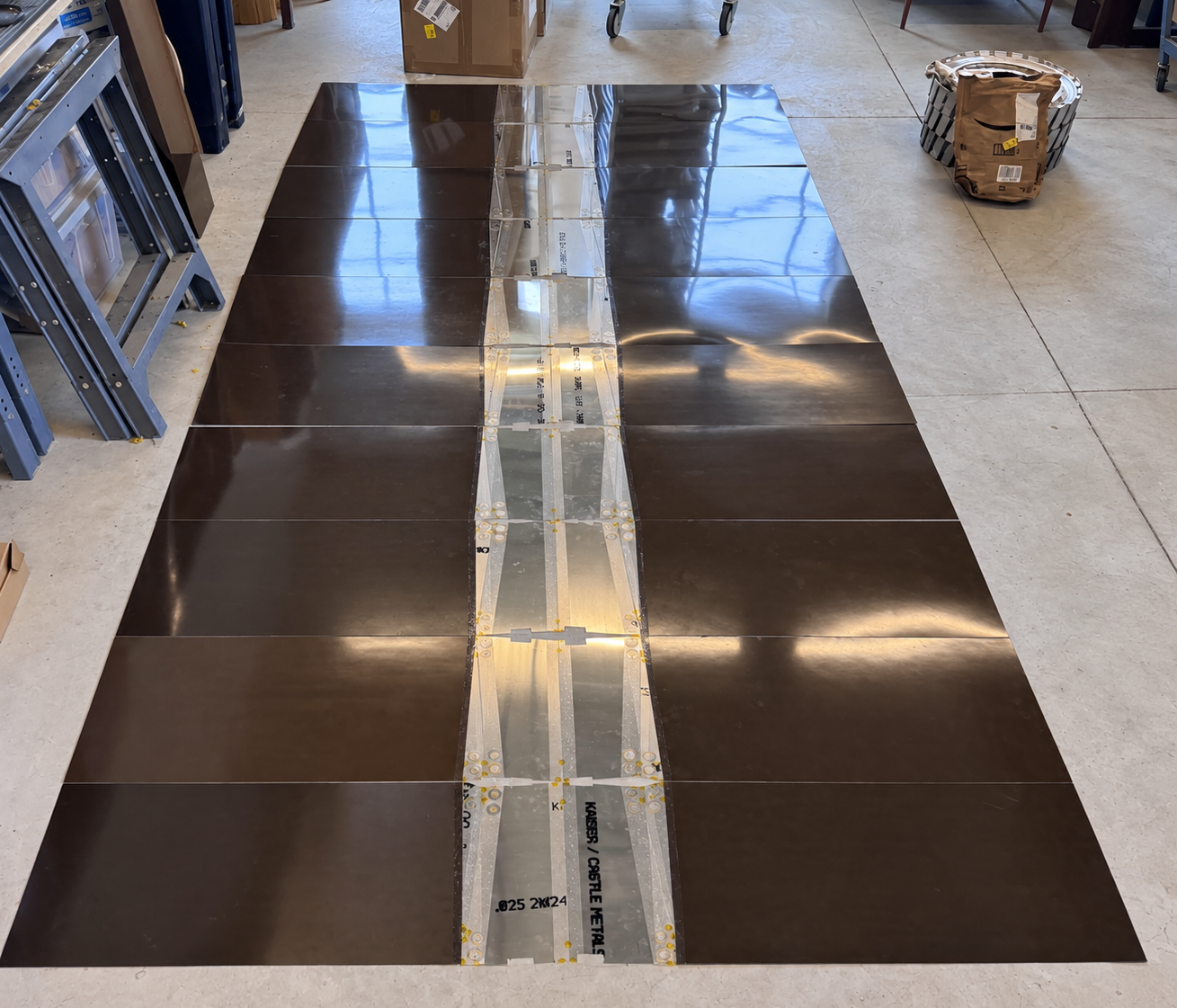
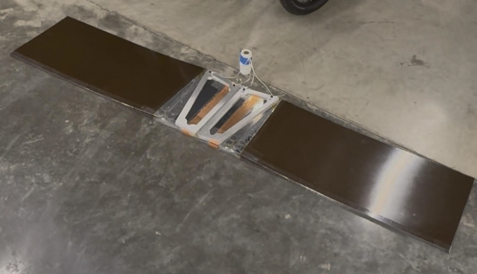
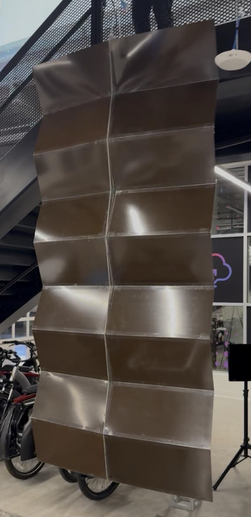
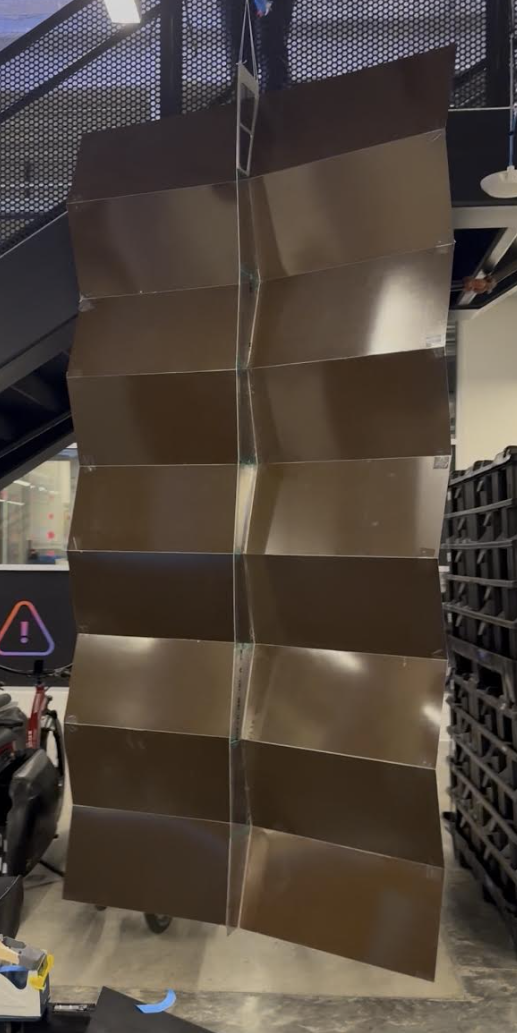
MK3 used Garolite panels selected to represent the thickness, mass, and stiffness of representative solar module stacks, joined with 50 µm PET hinges. A 900 µm aluminum spine and magnetic panel latching supported the configured 2A assembly. It measured 310 cm long × 150 cm wide deployed and 9 mm thick when bonded and stowed.
MK3 was a mechanical analog of a solar wing. Its Garolite panels represented the module stack mechanically; the prototype did not generate photovoltaic power.
The demonstration established the ability of local groupings to articulate and position a global aperture at a flight-relevant scale. MK3’s first structural mode was estimated to be approaching or above 1 Hz, potentially well above, but was not explicitly measured. The photographs document the flat assembly, compact stowed stack, and deployed front and rear surfaces.
Flat assembly
Bonded and stowed · 9 mm thick
Deployed front
Deployed rear
Together, the prototypes provide physical evidence for fabrication, articulation, and aperture arrangement. Their Garolite panels are mechanical analogs. Solar performance estimates use the common module baseline; the prototypes provide mechanical validation.
Unfolding, deployment, and structural constraints
Unifold’s structural benefit comes from section geometry, but its material and joints remain flexible. Finite section depth provides a basis for stiffness; load capacity still depends on the material, connections, deployed geometry, and stability of the section.
Thickness and buckling
Unifold is not inherently thick-foldable in every configuration. Asymmetric vertices can require specialized joints to accommodate thickness. In the intended thin structures, panel dimensions exceed thickness by roughly 100–1,000 times, so a thin-folding model remains useful. Small relief around vertices can mitigate excessive strain; finite-thickness interference and joint strain still require evaluation for the chosen embodiment. Low panel and joint bending stiffness also permits buckling of longitudinal stiffeners.
Deployment assistance
Global deployment requires an applied driving influence. Candidate approaches include inertial deployment, gravity-gradient deployment, and hydraulic joint actuation inspired by insect wing and elytron deployment. These offer ways to extend the aperture without relying on sufficient elastic energy stored within the folded surface. Local magnetic repulsion may initiate opening; the selected assistance method must drive and control deployment of the full aperture. The choice depends on the application and operating environment; gravity-gradient deployment is specific to orbital use.
Deployment assistance must be evaluated together with the folded shell, its joints, and its operating loads. The illustrated configurations establish geometric and mechanical concepts, not qualified load ratings.
Beyond this case study
The aerospace examples demonstrate what may be enabled when fold geometry, manufacturing, deployment, and the active surface are considered together. Similar performance gains may be discovered in other fields through an equally comprehensive approach to the application. Deployable apertures, shelters, and shields on Earth and in space offer different requirements and opportunities for that exploration.
References and image credits
The references below credit the external imagery used in the design comparisons. Packing and deployment assessments are the author’s comparisons, not conclusions attributed to these papers. Unifold diagrams and design renderings are by Degrees of Freedom LLC.
- Alden Yellowhorse, Robert J. Lang, Kyler Tolman, and Larry L. Howell (2018). Creating Linkage Permutations to Prevent Self-Intersection and Enable Deployable Networks of Thick-Origami. Eggbox imagery.
- Jingyi Yang, Yunlan Zhang, Manolis N. Chatzis, and Zhong You (2022). Folding and deploying identical thick panels with spring-loaded hinges. Hamiltonian-circuit imagery.
- Yi Zhu and Evgueni T. Filipov (2024). Large-scale modular and uniformly thick origami-inspired adaptable and load-carrying structures. Yoshimura imagery. Author spelling follows the published paper.
- Long Huang, Peng Zeng, Lairong Yin, and Juan Huang (2022). Design of an origami-based cylindrical deployable mechanism. Waterbomb/eggbox imagery.
- Zhongyuan Wang, Robert J. Lang, and Larry L. Howell. Bloom patterns: radially expansive, developable and flat-foldable origami. Bloom-pattern image credit.
- Yan Chen, Rui Peng, and Zhong You. Origami of thick panels. Thick-panel image credit.
Version history
| Version | Description |
|---|---|
| V1.0 | Initial Release |